Pro Brace Hydraulic Frame
SAVE INSTALLATION TIME AND COST
Pro-Brace Hydraulic Frame
PRO-BRACE HYDRAULIC FRAME
The Pro-Brace Hydraulic Frame system dramatically decreases the installation and removal time when compared to traditional cut and weld frame projects. Designed with the ability to use a number of interlocking sheeting types, the Pro-Brace Hydraulic Frame allows end users to use existing interlocking sheet pile stock.
Pro-Brace Hydraulic Frame System
Saves time and money when compared to traditional cut and weld systems
Pro-Brace Hydraulic Frame
The Pro-Tec Equipment Pro-Brace Hydraulic Frame dramatically decreases the installation and removal time when compared to traditional cut and weld frame projects. Designed with the ability to use a number of interlocking sheeting types, the Pro-Brace Hydraulic Frame allows end-users to use interlocking sheet pile stock.
Ideal for use on projects such as:
- Linear applications
- Pump stations
- Tank installations
- Bridge footings
- Large cast-in-place projects
- Many, many more
Pro-Brace Components
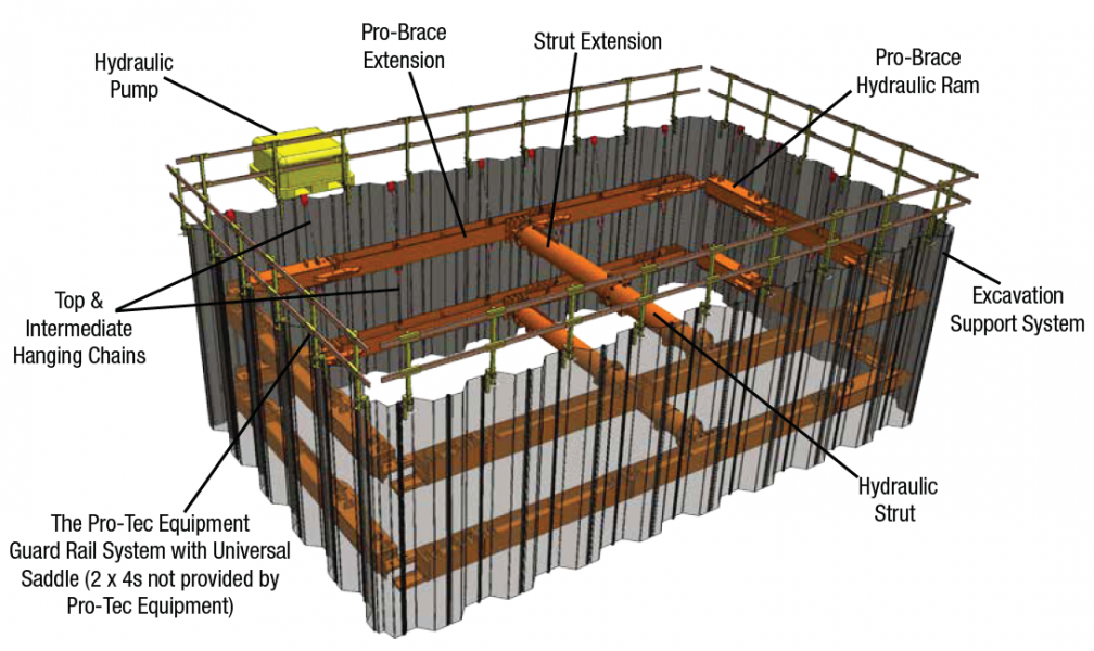
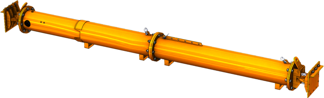
The Pro-Brace Hydraulic Ram
A 6” aluminum dual-acting cylinder encased in steel box tubing, the ram provides an operating
range of 9’8” (2.9m) to 13’1” (3.9m). The adjustability of the Pro-Brace enables a variety of excavation shapes to be safely shored.
The Pro-Brace Extension
Paired with the Pro-Brace Hydraulic Ram, the extension is a static component that allows for an array of lengths. Available lengths include:
- 3’3” (1m)
- 4’11” (1.5m)
- 9’10” (3m)
- 16’4″ (5m)
- 22’11” (7m)
- 32’9″ (10m)
The Hydraulic Strut
The Hydraulic Strut (available in multiple capacities), allows the complete system to achieve larger standard and custom sized projects.
The Strut Extension
Designed to be used in conjunction with the Hydraulic Strut, the Strut Extension provides extra length, when needed.
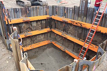
Top & Intermediate Hanging Chains The Hanging Chains act as a fail-safe if the system where to lose pressure and the Intermediate Chain are used for projects requiring multiple levels of rams.
The Pro-Tec Equipment Guard Rail System Serving as an extra precautionary measure, providing temporary railing around excavations and trenches.
Hydraulic Pump
A gas powered, dual-acting pump capable of producing 2,500 psi in both directions. The Hydraulic Pump includes 30’ long hoses with quick disconnect sockets.
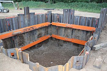
Excavation Support System
The Pro-Brace is designed to use variety of approved shoring components (sheet pile, beam and plate), increasing the overall usability.
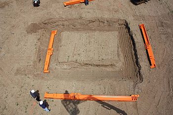
General Installation Steps
Step 1
Dig initial pilot cut (2-3’) and stage one leg of the Pro-Brace Hydraulic Rams. If using multiple levels of rams, they may be stacked upon each other to speed up installation time.*
Step 2
Assemble initial ram and extensions. If using multiple levels of rams, assemble the rams and extensions and stack on top.
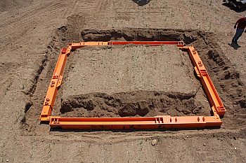
Step 3
With top level assembled, begin placement of excavation supports systems.
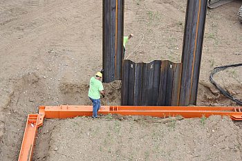
Step 4
With all supports installed, connect the top level of the Pro-Brace to the bracing supports with Hanging Chains and pressurize system.
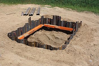
Step 5
If using multiple levels, excavate to next ram spacing and pressurize system.* Repeat until all rings are installed and pressurized.
Step 6
With all rings in place, excavate down to project depth.
*Site-specific engineering is required on all Pro-Brace projects. A Registered Professional Engineer will determine the number of braces, spacing and allowable system depth, based upon soil and jobsite
conditions.
Pro-Brace Configurations
Possible Configurations
The Pro-Brace Ram, a dual acting 45-Ton capacity hydraulic system and the static extensions, enable connections that allow for a wide range of widths and lengths combinations. The chart below shows examples of ram and extension combinations and the lengths they achieve. Note, the chart shows just a sampling of the combinations, other combinations can be done to provide desired width.

Pro-Brace Hydraulic Strut
Hydraulic Struts
Available in 100T and 165T models, the Hydraulic Strut, when used in conjunction with the Pro-Brace System, enables large and custom sized projects to be completed with relative ease.
Both strut options contain dual acting hydraulic struts, providing exacting adjustments and swivel end attachments, enabling them to be used as either a center strut or a corner strut.
18″ 100 Ton Capacity Hydraulic Strut
| Model | Description | Minimum Length | Maximum Length | Weight |
|---|---|---|---|---|
| Model | Description | meter | meter | kg |
| 18-100T | 100T Strut | 2.82 | 3.99 | 1308.61 |
Strut weight includes swivel attachment
Bolt on Strut Extensions
| Model | Description | Length | Weight |
|---|---|---|---|
| Model | Description | meter | kg |
| 18-1 | 1 Meter Extension | 0.99 | 181.44 |
| 18-1.5 | 1.5 Meter Extension | 1.52 | 233.60 |
| 18-2 | 2 Meter Extension | 1.98 | 288.03 |
| 18-3 | 3 Meter Extension | 3.00 | 392.36 |
| 18-6 | 6 Meter Extension | 6.00 | 784.71 |
20″ 165 Ton Capacity Hydraulic Strut
| Model | Description | Minimum Length | Maximum Length | Weight |
|---|---|---|---|---|
| Model | Description | meter | meter | kg |
| 20-165T | 165T Strut | 3.56 | 4.75 | 2701.14 |
Strut weight includes swivel attachment
| Model | Description | Length | Weight |
|---|---|---|---|
| Model | Description | meter | kg |
| 20-.5 | .5 Meter Extension | 0.48 | 172.36 |
| 20-1 | 1 Meter Extension | 0.99 | 233.60 |
| 20-2 | 2 Meter Extension | 1.98 | 349.27 |
| 20-4 | 4 Meter Extension | 3.96 | 596.47 |
| 20-8 | 8 Meter Extension | 8.00 | 1065.94 |
Contact Pro-Tec
Why Pro-Tec Equipment

Pro-Tec Equipment is designed with superior quality, safety, dependability and durability in mind. We have continued to expand our range of equipment and services to ensure you, our customer, have what you need to meet the constant challenges you face at the worksite. Your success is our success.
Learn MoreDownload Product Literature
Downloadable PDFs of our product lines.
Related Literature:
-
PRO-BRACE HYDRAULIC FRAME
*PSF (pounds per square foot) ratings indicate maximum shield capacities. Depths are based on B, C and C-80 soil types as described in OSHA’s 29 CFR Part 1926 Subpart P, October 31, 1989 with Type B not exceeding 45 PSF per foot of depth, Type C not exceeding 60 PSF per foot of depth and Type C-80 not exceeding 80 PSF per foot of depth. Determine actual soil pressure and consult manufacturers Tabulated Data prior to each use.
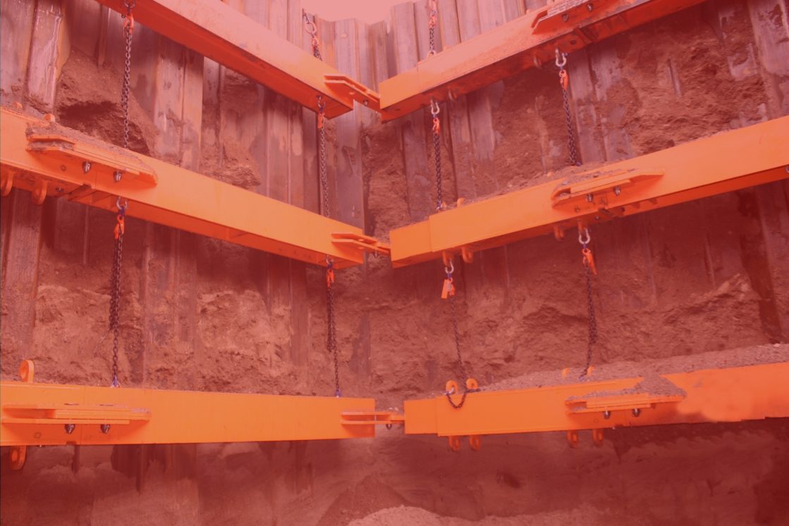
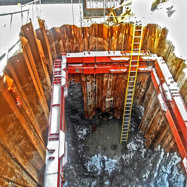
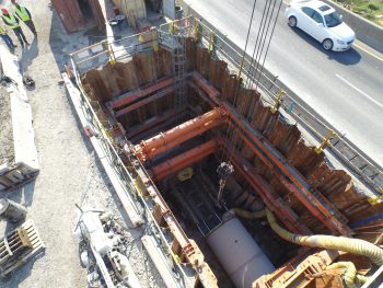
Job site photos are strictly intended for general product information only and may not comply with all applicable safety standards. Always refer to manufacturers’ serialized specific tabulated data, O.S.H.A. 29 CFR 1926 Subpart P for excavations and all applicable safety standards prior to each use.